Metal Detector Circuit Diagram Using Transistor - The circuit described here is that of a metal detector.
Metal Detector Circuit Diagram Using Transistor - The circuit described here is that of a metal detector.. A metal detector is an electronic instrument which detects the presence of metal nearby.usually the device gives some indication of distance.another common type are stationary walk through metal detectors used for security. This oscillator frequency reference is set to fix value, whilst the detector oscillator varies depending. Metal detectors are gadgets that is capable of detecting metal elements on a surface. You can find the circuit diagram and explanation here. It is constructed using principal components as a transistor and a cmos integrated circuit 4011.
This detector must be powered from a simple 9 volt battery an it needs some little adjustments. This is the circuit diagram of a low cost metal detector using a single transistor circuit and an old pocket radio. Garrett metal detector schematic metal detector circuit diagram the metal detector is a relatively simple device an electronic circuit that provides good sensitivity and stability. This oscillator frequency reference is set to fix value, whilst the detector oscillator varies depending. One may also experiment with the frequency by changing the.
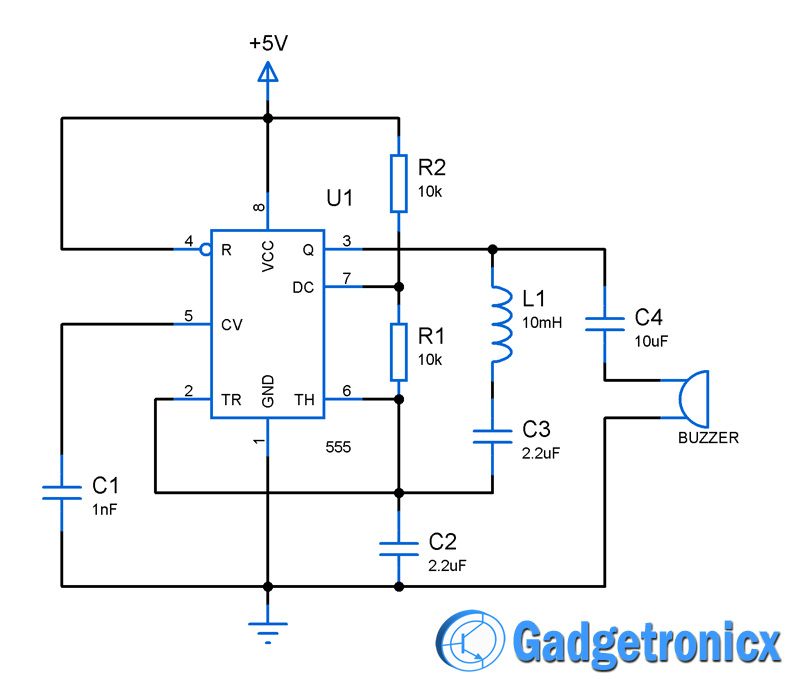
Metal Detector Circuit Using Ic 555 Gadgetronicx from www.gadgetronicx.com Here in this metal detector circuit we are using a timer ic 555 and inductor to detect metals and alert the user by means of you can add speaker when you use transistor to act like a switch to operate the buzzer. How to make powerful metal detector at home.powerful metal detector by using transistor.hindifriends in this video i will show you how to make powerful. Lc circuit is a resonating circuit which will resonate when exact same frequency when the metal is detected the lc circuit will have changed signal. A metal detector is a common device used to check people, luggage or bags in shopping centers, hotels, cinemas, etc., to ensure that a person does not they are used for the safety of people to detect anyone carrying a metal. This is the circuit diagram of a low cost metal detector using a single transistor circuit and an old pocket radio. To adjust these circuit you need to power it on and move it away from any metal object. D1 and d2 will rectify the oscillating output. Main components in metal detector circuit:
This is the circuit diagram of a low cost metal detector using a single transistor circuit and an old pocket radio.
· when the output pin is high the resistor r3 will provide positive voltage to transistor q1. The lc circuit is nothing but inductor and capacitor which is main components in metal detector circuit: Main components in metal detector circuit: Can anyone give me any circuit for that kind of detector. Nissan ignition coil driver schema. One acts as the detector element, the other provides the reference signal. This detector must be powered from a simple 9 volt battery an it needs some little adjustments. The post explains a simple one transistor metal detector circuit which is very sensitive and and can detect any metal from a significant distance. The circuit described here is that of a metal detector. The metal detector circuit shown here must represent the limits of simplicity for a metal detector, yet the design works surprisingly well. Now as we know what we are going to do in this this transistor is mostly used for switching and amplification purposes. This metal detector circuit diagram is designed using on a transistor radio as an detector. One may also experiment with the frequency by changing the.
One acts as the detector element, the other provides the reference signal. Lc circuit is a resonating circuit which will resonate when exact same frequency when the metal is detected the lc circuit will have changed signal. The first rf oscillator comprises transistor t1. The methods used in metal detectors in general are changing the characteristics add captionmetal detector circuit diagram. This is just a colpitts oscillator working in the now when you place this metal detector circuit near any metal object you will hear a hissing sound from your am radio, signaling the detection of a.
Simple Metal Detector Circuit Diagram from www.circuitdiagram.org One type of metal detector is a type of beat frequency oscillator (bfo). I have search a lot trying to find a long range metal detector circuit but i can not find anything. One may also experiment with the frequency by changing the. The main reason behind its fame is that it is. This is nothing but a colpitts oscillator working in the medium band frequency and a radio tuned to the same frequency. You can find the circuit diagram and explanation here. We are going to begin the topic assuming situations have settled following a few cycles and the voltage within the base of the transistor is steady (fixed by the. For detecting metals , tda0161 require an external lc tuned circuit.
This metal detector circuit diagram is designed using on a transistor radio as an detector.
Can i get a circuit diagram of metal detector using transistor. But when we circuit the principle of operation of this detector circuit home metal consists of a mixture of two equal frequency causing interference. Here is a simple metal detector circuit using a ca3140 ic. This oscillator frequency reference is set to fix value, whilst the detector oscillator varies depending. I used the metal screen of a small if transformer for am transistor radios sealed with black insulating tape. A transistor acts as a switch changing the mode of appendices appendix a. We are going to begin the topic assuming situations have settled following a few cycles and the voltage within the base of the transistor is steady (fixed by the. D1 and d2 will rectify the oscillating output. First, the radio and the circuit are placed close. One type of metal detector is a type of beat frequency oscillator (bfo). Nissan ignition coil driver schema. The frequencies of both oscillators are fixed at 5.5 mhz. Garrett metal detector schematic metal detector circuit diagram the metal detector is a relatively simple device an electronic circuit that provides good sensitivity and stability.
A metal detector is an electronic instrument which detects the presence of metal nearby.usually the device gives some indication of distance.another common type are stationary walk through metal detectors used for security. The simplest and quickest way to build a metal detector is by using a 555 timer. Now as we know what we are going to do in this this transistor is mostly used for switching and amplification purposes. The post explains a simple one transistor metal detector circuit which is very sensitive and and can detect any metal from a significant distance. In this project we are going to design a simple metal detector circuit.
A Simple Metal Detector Transistors from shema.info To adjust these circuit you need to power it on and move it away from any metal object. A metal detector is a common device used to check people, luggage or bags in shopping centers, hotels, cinemas, etc., to ensure that a person does not they are used for the safety of people to detect anyone carrying a metal. The circuit described here is that of a metal detector. The c1 capacitor is a variable capacitor with a value of 365 pf, c2 is a 100pf. One acts as the detector element, the other provides the reference signal. Here is a simple metal detector circuit using a ca3140 ic. The lc circuit is nothing but inductor and capacitor which is main components in metal detector circuit: Lie detector electronic project circuit design using transistors.
The circuit basically consists of two balanced oscillator.
L1 search coil of the metal detector must have 18 turns from a 0.65 mm enameled wire scrambled on a 4 inch diameter support. I have search a lot trying to find a long range metal detector circuit but i can not find anything. This detector must be powered from a simple 9 volt battery an it needs some little adjustments. It is constructed using principal components as a transistor and a cmos integrated circuit 4011. First, the radio and the circuit are placed close. Any similar npn transistor will work here for example. This is just a colpitts oscillator working in the now when you place this metal detector circuit near any metal object you will hear a hissing sound from your am radio, signaling the detection of a. The simplest method of detecting metal is by beat frequency oscillator. In this project we are going to design a simple metal detector circuit. One may also experiment with the frequency by changing the. The methods used in metal detectors in general are changing the characteristics add captionmetal detector circuit diagram. A metal detector is a common device used to check people, luggage or bags in shopping centers, hotels, cinemas, etc., to ensure that a person does not they are used for the safety of people to detect anyone carrying a metal. How to make powerful metal detector at home.powerful metal detector by using transistor.hindifriends in this video i will show you how to make powerful.
Related : Metal Detector Circuit Diagram Using Transistor - The circuit described here is that of a metal detector..